|
|
|
FEATURES
|
|
- Self Aligning
- Self Gapping
- Resolution 20 - 1250 pulses per revolution
- Frequency response to 200 KH
- Positive lock on cover
Wide Selection of Hub Bore sizes and terminations
12 Month Warranty
|
|
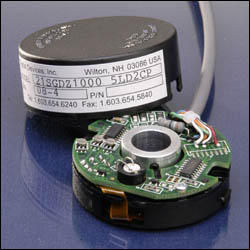
DESCRIPTION
|
|
The 21SG series Modular is highly reliable, low cost encoder using the latest SMT technology.
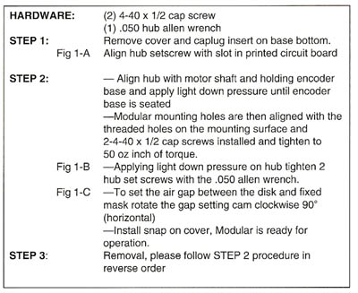
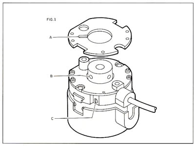
Installation and set-up is dramatically simplified with the gap/cam mechanism. The modular is aligned and gapped with the clockwise 90∞ turn of the cam. No further adjustments are required.
The positive snap on cover feature is convenient and eliminates hardware.
|
|
ELECTRICAL
|
|
- Code— Incremental
- Resolution—20-1250 cycles per revolution
- Supply Voltage—Vs (±5% ) + 5 or +12
- Supply Current—140 MA max
- Light Source—LED
- Output Format
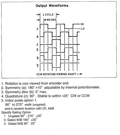
- Two count channels electrically phased 90° ± 25°
- One (optional) Zero Reference signal see fig#2
- Output Signal
- Vhigh=Vs thru 4.7K pull-up
- Vlo = .5 volts max
- Rise/fall time 1.0 µsec max
- Symmetry (duty cycle)—180° ± 10°
- Frequency Response—0 -200 KHz
- Output Device
- TTL 7404
- TTL 7406 Open Collector
- CMOS — MC4069
- Line Driver SN 75183D or 26LS 31CM
|
|
MECHANICAL
|
|
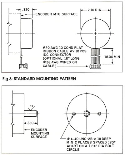
- Dimensions— See outline drawing fig#2
- Weight—2 oz. max
- Moment of Inertia—1 x 10⁻⁴ oz.-in. sec2
- Hub Bore Size
- Nominal 1/4", 3/8", 1/2", 5/8" are standard, special sizes and mm diameters are available
- Operating Temp.
- 0° to 70°C (32° to 158°F)
- -25° to 85C (-13° to 190°)F
- Slew Speed —10,000 rpm
- Accuracy — ±.2 min of ARC
- Materials— Lexan - Glass Fill
- Code Disc Material— Acrylic , Glass, Metal
|
|
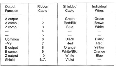
ELECTRICAL CONNECTIONS |
|
|
|
OUTPUT CHARACTERISTICS |
|
|
|
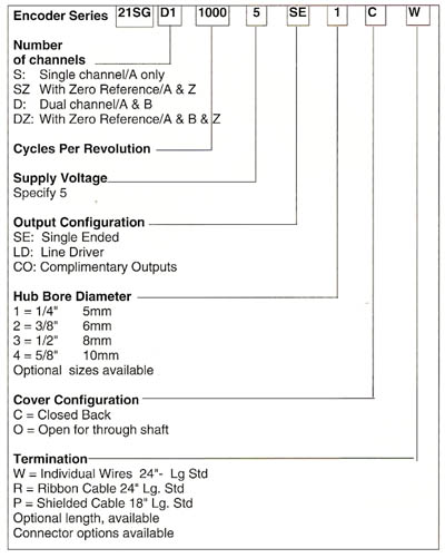
ORDERING INFORMATION |
|
|
|
OUTLINE DIMENSIONS |
|
|
|
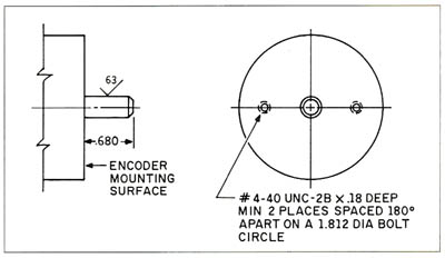
STANDARD MOUNTING PATTERN |
|
|
|
MOUNTING INSTRUCTIONS |
|
|
|
FIGURE 1 |
|
|
|